Ambiguous Feelings - Update 1
Progress⌗
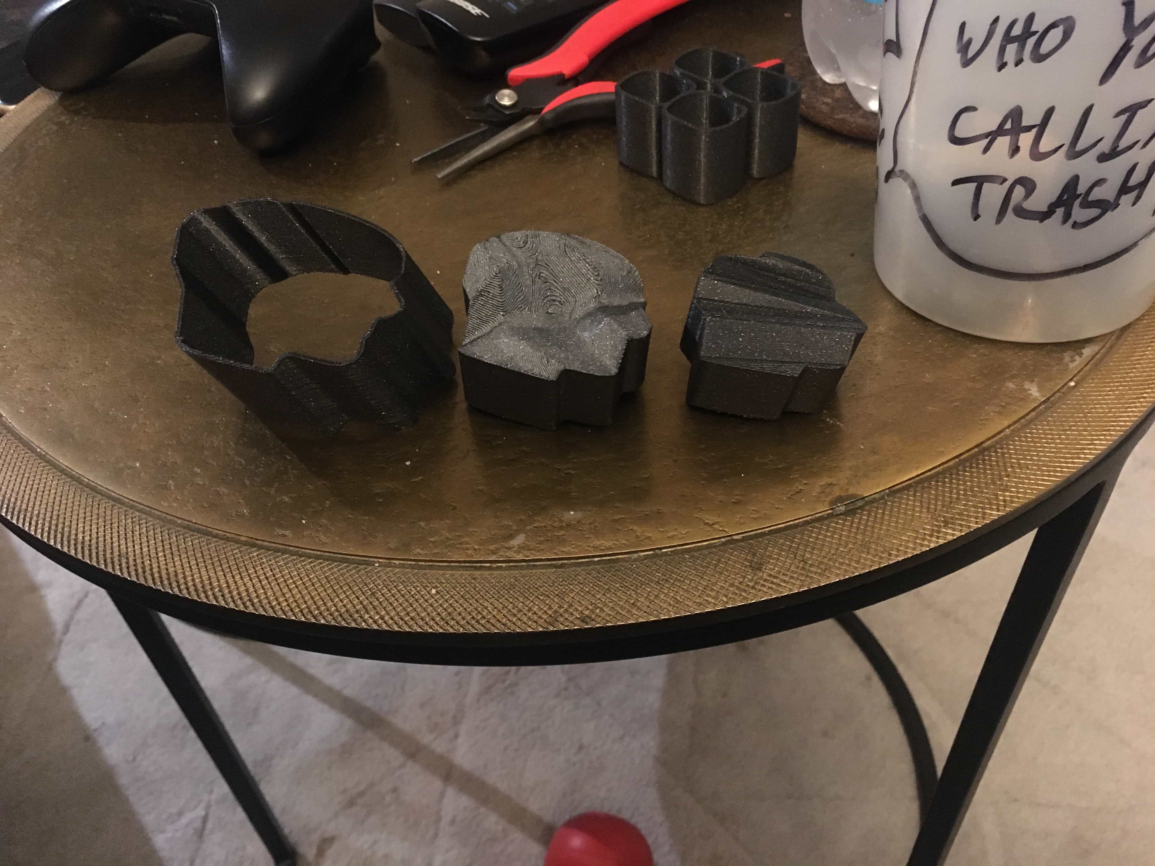
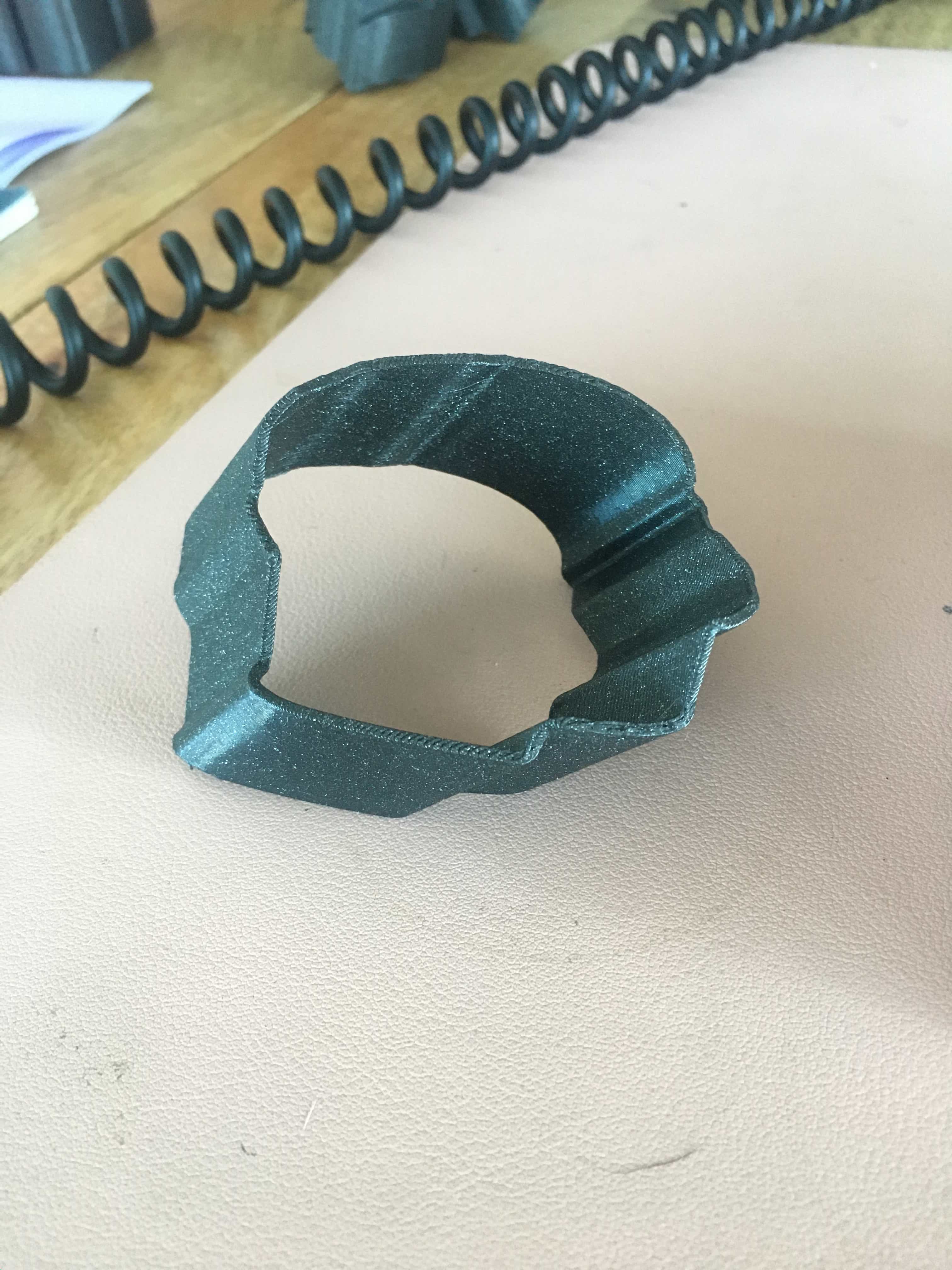
I have a physical object! It’s not perfect, but I made it, and the illusion kinda works!
This was the first big hurdle: could I take two simple images and create something like the ambiguous cylinder illusion from them.
The following is how I made the 3D prints I currently have.
The Process - v1⌗
So, there are many steps to this. It’s a real pipeline.
I originally was trying to find a way to use the equations Kokichi Sugihara lays out in his papers on the illusion. I was making some progress, but it was slow.
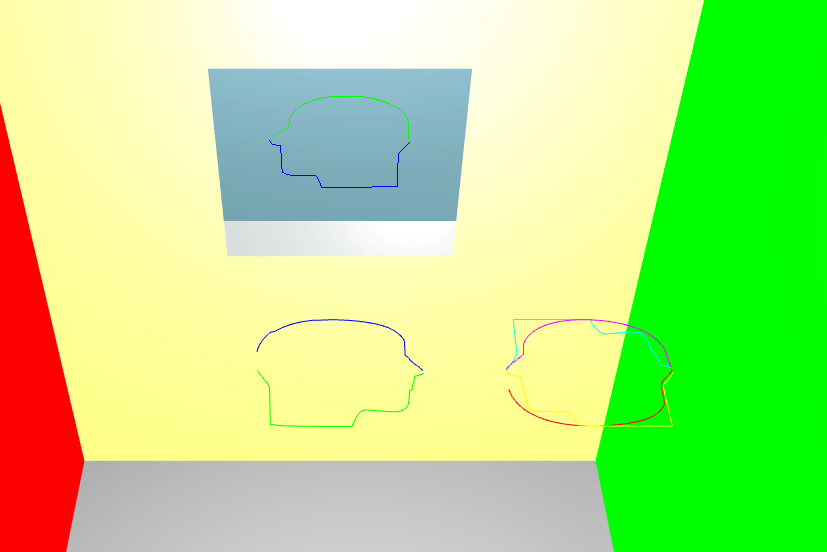
I decided to see if anyone had shared open source code for implementing this illusion. To my genuine surprise, I found one repo: Matsemann/impossible-objects. It runs as in the browser, takes two SVGs as inputs, and outputs a 3d render of the final shape. The shape is just a curved line made of vertexes. The code use three.js to create the 3D environment.
The code originally outpupt the data as .obj but this it lacked all the data that Vectorworks needed. So I changed it to output JSON which I would use later.
Steps⌗
Step 1
Create SVG’s from the images to use. In the repo I found were some example adobe illustrator files showing how to generate the SVGs.
The code expects a certain scale for the SVGs. Second, it expects two SVG’s each cut in half, for a total of 4 parts (so technically it really requires four SVGs).
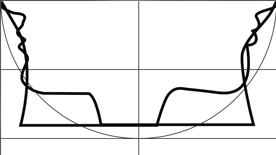
For my first test I used these two images (a) and (b). I imported them into illustrator and outlined them. I then scaled them to the correct size, chopped them in half, and exported them as SVGs.
Step 2
I updated the code two use my SVGs. The code also comes with helper functions to invert, shift, and a couple other transformations that can be used to make the final output.
Once the rendering looked good, I opened up the browsers developer tools. I printed a key on the window object which I changed the code to store the JSON data in. I copied that and pasted it into a JSON file.
Step 3
Having this data was great, but I wasn’t sure it was going to work. To test it, I wrote a quick jupyter notebook (python) to plot the data. It worked! Knowing this, I need to get the data into a format that Vectorworks would like.
Step 4
I used Processing to read in the JSON data, draw the vertex’s, and output the result in the .dxf format.
import processing.dxf.*;

JSONArray json;
JSONArray values0;
JSONArray values1;

int scale = 100;

// TODO: how to use
// 1. set `output_name`
// 2. set `fill` to true if want faces

String output_name = "00_faces_no_fill.dxf";
boolean fill = false;

void setup() {
  size(1000, 1000, P3D);
  background(0);

  beginRaw(DXF, "./output/" + output_name);

  translate(width/2, height/2, 0);
  rotateX(PI/2);
  rotateZ(-PI/6);

  stroke(255);

  if (!fill) {
    noFill();
  }

  beginShape();
  drawObject();
  endShape();
  endRaw();
}

void drawObject() {
  obj();
  ary(values0);
  ary(values1);
}

void obj() {
  json = loadJSONArray("../data/faces.json");

  values0 = json.getJSONArray(0);
  values1 = new JSONArray();
  JSONArray tmp = json.getJSONArray(1);


  // reverse second array so end and start points line up
  for (int i = tmp.size() - 1; i >= 0; i--) {
    JSONObject tmp_obj = tmp.getJSONObject(i);
    values1.append(tmp_obj);

    // connect back to starting point
    if (i == 0) {
      values1.append(values0.getJSONObject(0));
    }
  }
}

void ary(JSONArray values) {
  for (int i = 0; i < values.size(); i++) {

    JSONObject points = values.getJSONObject(i);

    float x = points.getFloat("x");
    float y = points.getFloat("y");
    float z = points.getFloat("z");

    vertex(x * scale, y * scale, z * scale);
    print(x * scale);
    print(" ");
    print(y * scale);
    print(" ");
    println(z * scale);
  }
}
Step 5
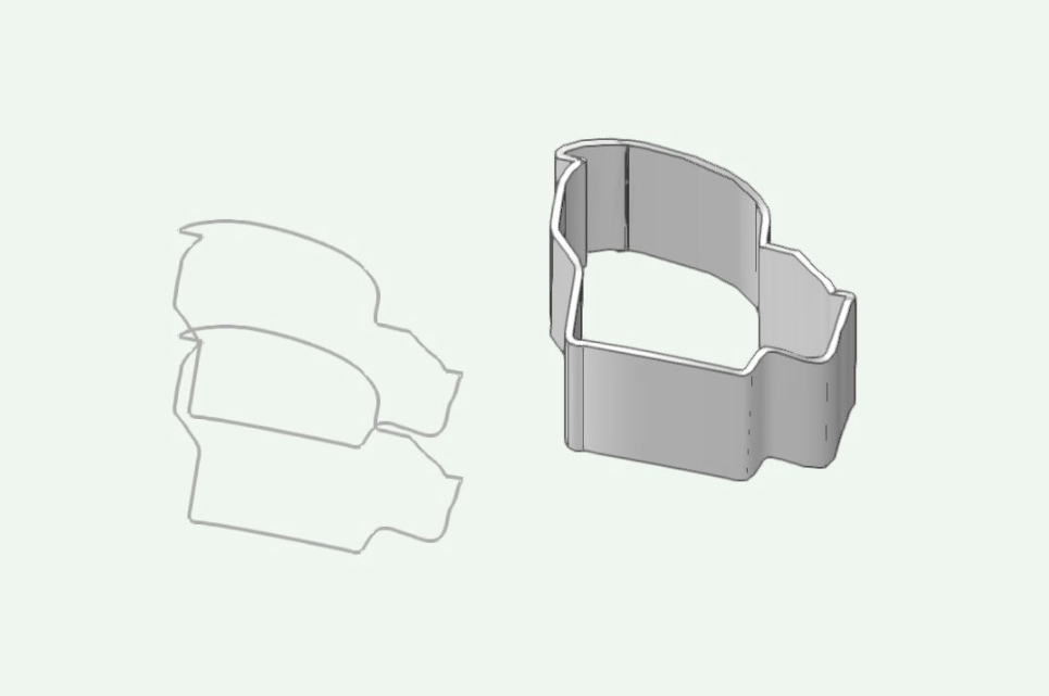
The next step was to import the DXF file into Vectorworks. That’s the easiest part of step 5.
The data imports as many (in this case +400) 3D Polylines. I need a solid object. After lots of internet searching, meeting with Dani and a few emails back and forth, I did evntually figure out how to create the shelled, solid object I was looking for.
Here is a rough overview of those steps
- import DXF as 3D - arrives as many 3d polygons
- close them and compose - get one 3D polygon
- check the closed box in the info, not sure it makes a difference
- convert to nurbs
- rebuild NRUBS in the 3d power pack to about 100 (simplifies it)
- duplicate the NURB about 100 under (z-axis)
- loft without rail
- in the 3d tab of the tools menu, choose leave curves and not solid
- the angle (0 - 90) determines the angle of the wall built (0 for both is vertical)
- ungroup the resulting shape
- move NURBS surface to it’s own space
- shell solid tool (outside)
Step 6
Once the rendering looks correct, I exported the object as a .stl file.
I then took the STL file and imported into a slicer (I used the PrusaSlicer).
The scale was wrong - the object was huge. But for the sake of testing, I just scaled it down to fit on the print plate.
Step 7
Once the object looked good in the slicer, I exported the object as .gcode.
I loaded the gcode ont my 3D printer (Prusa Mini) and printed it!
Whats Next⌗
The next step is to refine the process and figure out what kinds of things effect the clarity of the illusion. Size, fill vs no fill, lighting, and so on.